s2000 cluster project
- Thread starter konerri
- Start date
tuned86
New Member
Cool mate, im also in Vic....though never heard of Robinvale keke, sure its somewhere around. 
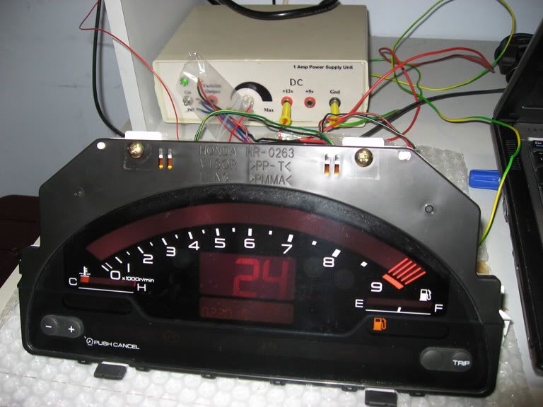
Just powered up the cluster, looks awesome!
B4, B5 = 12V
B8, B9 = ground
Empty Fuel, SRS and ABS was on. I think I will just remove the globes to keep wiring minimalistic.
I read up on ICSP which is quite interesting. So with a 16F877A (and a few others), you can basically get a breadboard, ICSP connector and wire it accordingly to ICSP protocol and directly program the microchip on the board without using a chip programmer? Essentially you could prototype on the breadboard the exact circuit you want to build using ICSP model.
How do you obtain 13V on MCLR from a 12V source. Is that possible using a IC Voltage Regulator?
(For those who object to me posting such newbie questions, let me know and I can take this offline but I figured people who were not at the advanced stage could appreciate the same learning curve to get into this project as well)
orthello
The Dutch Guy
Robinvale is very very close to the New South Wales border. (100km south east of the Mildura region)
Find the spot where the Murray Valley HighWay (B400) crosses the Murray River and connects to the Sturt Highway (20) and there you'll find Robinvale.
My programmer has an ICSP connector with MCLR. It getting it's voltage from an external source (laptop adapter in my case)
Some PICS are able to use low voltage programming. 16F877A is able to do that, but you need to set it to that mode first. And for that first step you still need a 'high' MCLR voltage.
I'm not sure, but I was in the impression that 12V was enough for MCLR. (everything higher the 5v will do.... as far as I know! I'm not completly sure about this last statement)
tuned86
New Member
Ah, yes thats bit far away from the metropolitan  Sounds like you've been to Oz?
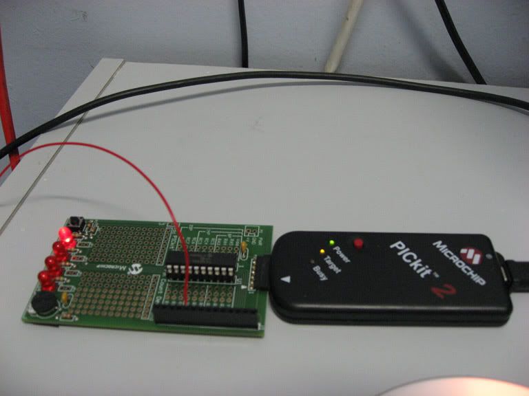
After some studying I decided to get a pickit2 programmer for simplicity (newbie me).

After some blinking code modifications:


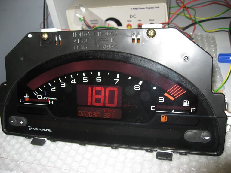
I couldn't get it to display any higher than 180...maybe the limit for this JDM cluster since most JDM cars limit around 180?
I want to build a running counter to count from 0-300 (or maybe 180 in my case). That way I can build a routine to 'DisplaySpeedo(x)' and use it like the korreni's idea of displaying water, oil temps and pressure
After some studying I decided to get a pickit2 programmer for simplicity (newbie me).

After some blinking code modifications:


I couldn't get it to display any higher than 180...maybe the limit for this JDM cluster since most JDM cars limit around 180?
I want to build a running counter to count from 0-300 (or maybe 180 in my case). That way I can build a routine to 'DisplaySpeedo(x)' and use it like the korreni's idea of displaying water, oil temps and pressure
orthello
The Dutch Guy
I've not been there yet. My parents have. To visit my two uncles and family.Ah, yes thats bit far away from the metropolitanSounds like you've been to Oz?
.
.
.
That way I can build a routine to 'DisplaySpeedo(x)' and use it like the korreni's idea of displaying water, oil temps and pressure
I'm planning to go there within one or two years. And also do some scuba at the GBR, and hopefully see some light emiting jellyfish.
.
.
.
The 180km/h is weird. The gauge should reach 300km/h (or 180MPH) Hmmm... display is in mile or km mode? KM mode as far as I can see, right? Input signal is around 8kHz? 8kHz should make the display show almost 300km/h or 180MPH. I have a JDM AP1 gauge myself and didn't experience this behaviour.
Maybe mixed up the km and mile calculation in your converter upic?
Note that the DisplaySpeedo(x) thing also has effect on the TRIP and ODO counters.
When displaying temperatures, the ODO and TRIP counter keep adding in a certain rate. If it is a problem? I don't know. That is for yourself to decide. Keep in mind that it can make your TRIP and ODO counter offset for an additional few hundred meters everytime you want to see a temperature. For me that was a reason NOT to do it. I'm very well aware of the temperature/segment table I created in my upic. Every segment is like 10 degrees celcius. And it shows temperatures from 60 to 120 degress celcius.
tuned86
New Member
I think im just using the default 4hz internal clock. I'll play around with it more but at the moment im just toying around with some code to trigger so i don't understand half the things im doing.
You've got a good point about TRIP trigger, didn't really think about the repocussions. I've jumped over to the ECT coding since it looked a bit simplier...
I couldn't get any of the bars to light up. When you set to 'low', are you turning OFF output for 'x' ms?
I have been trying to trigger 7 bar using a Delay10 function (10 ms).
Turn On output
Delay 10 x 3
Turn Off Output
Delay 10 x 18
Repeat
plummo_vtec
New Member
well bugger me that is a step above bet that bit of kit cost an absolute fortune think i will stick to the s2k till im a millionaire or something
tuned86
New Member
wonder if he is watching the road while driving?
Bit of update:
I can control the Temp bars on the cluster using both wasted cycle delays or a timer control. I guess timer control is better as it free's up processor.
I am bit stuck on the speedo though. I could trigger it using wasted cycle, also finally got PWM to work.
I've am using the internal clock set at 2MHZ using a prescaler of /16 and I can generate 122hz with 50% duty cycle but the lowest the reading will go is 14km/hr ? Based on the recordings, shouldn't that frequency be under 10km/hr? Are you guys using PWM to output the speedo by changing, prescaler and period?
I am pretty definite that there is a 180km/hr limit on this cluster
tuned86
New Member
I think its coz im using the 16F690 using the internal 8MHZ clock and even though I set the internal clock to 4MHZ and prescale to 16, I the most i can prescale is 488.28hz which probably explains why.
I played around with some OSC frequency and it seems like (using prescaler of 1/16)
1MHz min 61 Hz
2MHz min 122 Hz
4MHz min 244Hz
tradeoff is you lose resolution in higher frequencies
I played around with some OSC frequency and it seems like (using prescaler of 1/16)
1MHz min 61 Hz
2MHz min 122 Hz
4MHz min 244Hz
tradeoff is you lose resolution in higher frequencies
Ominous G2
┌∩┐(◣_◢)┌∩┐
WTF is that! That would make David Hasselhoff weep.And we think an S2000 cockpit is cool?!?!
Check this german Toyota MR2 guy
orthello
The Dutch Guy
Ok here it comes.I think its coz im using the 16F690 using the internal 8MHZ clock and even though I set the internal clock to 4MHZ and prescale to 16, I the most i can prescale is 488.28hz which probably explains why.
I played around with some OSC frequency and it seems like (using prescaler of 1/16)
1MHz min 61 Hz
2MHz min 122 Hz
4MHz min 244Hz
tradeoff is you lose resolution in higher frequencies
When using a 4MHz clock the PWM module can only produce frequencies from 245 up to 35k.
When driving about 10km/h an output pulse of 250Hz must be produced. No problem.
But when driving slower, say 3 km/h you're having a problem producing 75 hz.
To solve this, you can make the pwm produce a frequency which is 4 times higer then needed. So when your driving 3km/h it will produce 300hz (instead of 75). 300hz is a valid frequency.
Now comes the trick..... on the out of the pic, add a counter (7490) and configure it to divide by 4. The ouput of the counter is the final signal which can be fed to the S2000 cauge. 300hz divided by 4 is 75Hz.
So this way you're able to produce lower frequencies, while your PIC is still limited to 245hz
Got it?
plummo_vtec
New Member
any more progress guys

