Kuchtaboy
Unregistered User
All pictures and write up in above quote is property of 95ATEG at Team-integra.net95ATEG said:Tools/Material's needed
-Dremel (metal nibblers from Radioshack will work also)
-Metal cutting blades
-Masking Tape
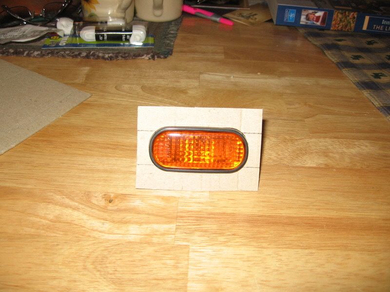
-Thin cardboard for Stencil for Sidemarker hole (as shown or your own)
-Wire Crimpers
-Sidemarker Harness (14-16guage wire)
-Wire connectors
-Shrink wrap (electrical tape)
-Safety Glasses
-Dry Erase Marker
-Ruler with mm or any measuring tool
-Primer or Clear sealer (protect from Rust)
-About 2 hours to spend with your Integra
Step 1:
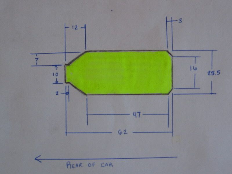
You will need to make some sort of stencil for your sidemarkers. I have taken the measurements from mine and drawn them up(as seen below) or you could measure for yourself.

Heres my stencil

Step 2:
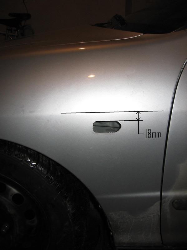
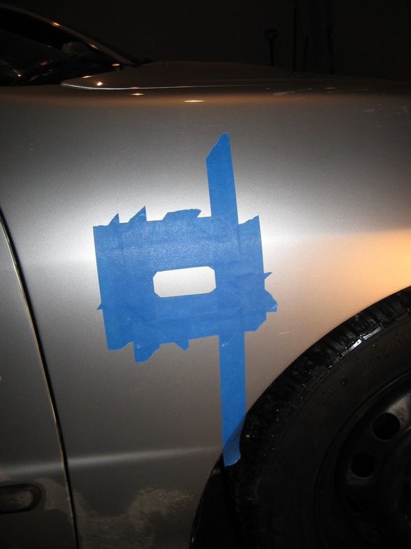
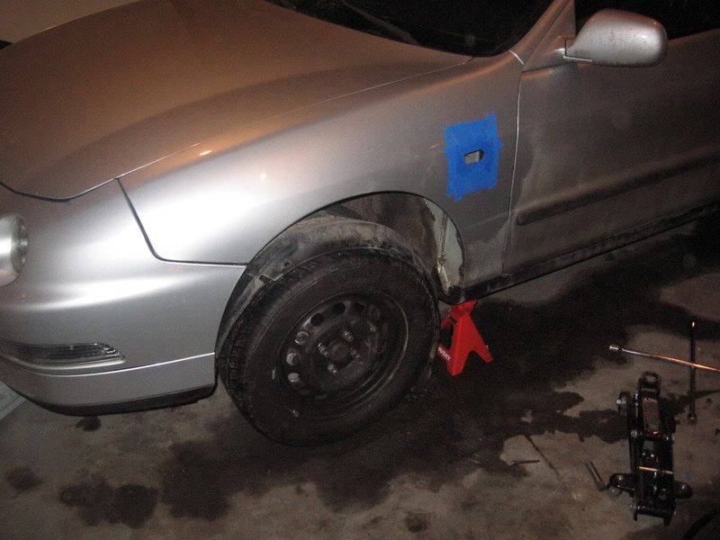
Now we will start masking off the area where we will begin cutting. You want to make the top of the side marker hole about 18mm below the body line...

So i would suggest, as I did, measure 18mm from the top of your cardboard and start your stencil there, that way you can use the top of the stencil as your guide for the body line. (Be sure that the stencil is made so the clip toward the rear of the car.)
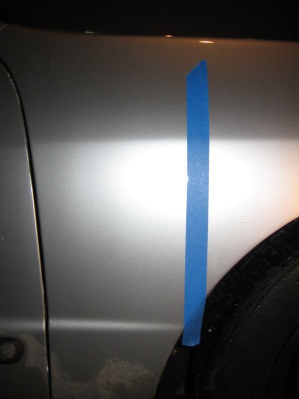
Place first piece of masking tape here...

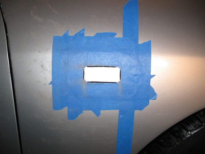
Then copy the stencil onto the fender with a dry erase marker to mask off the rest of the area. like so...

(My looks a little different from the measurements above because i wasnt sure exactly where cut for the clip.)
Repeat on opposite side of car.
Step 3:
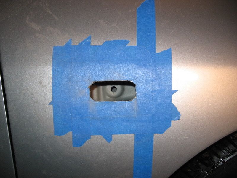
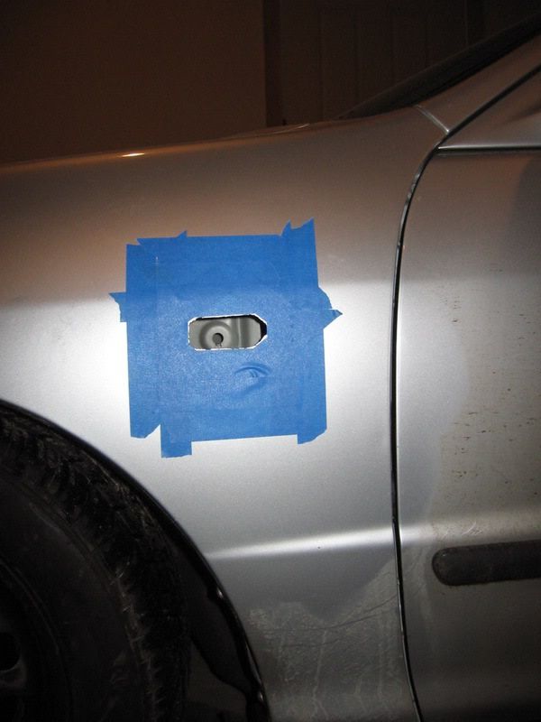
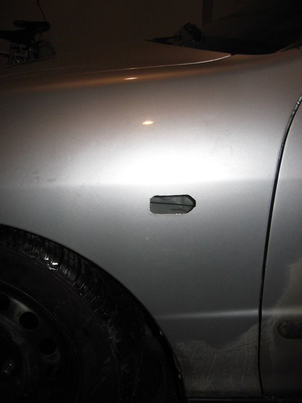
Once both side of the car are masked, its time to Measure Measure and Measure some more to make sure that all the dimensions in the tape border are correct. Now we can start cutting away. Start by cutting a square then start on the clip area, occasionally making sure that it isnt to big.Once it goes in stop cutting...Make sure your wearing your safety glasses!


***REMEMBER WHILE CUTTING TO MAKE SURE THAT THE SIDEMARKER IS FITTING NICELY. IF IT GOES IN STOP CUTTING. IT IS VERY EASY TO CUT TOO MUCH.***
Step 5:
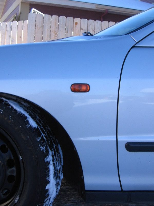
Now that the hole has been cut to size and the sidemarker fits snug, lightly file down the edges. Then cover the rest of the fender and door area to prepare for paint. Once the paint has dried you can remove all tape and check out the finished hole...

Step 6:
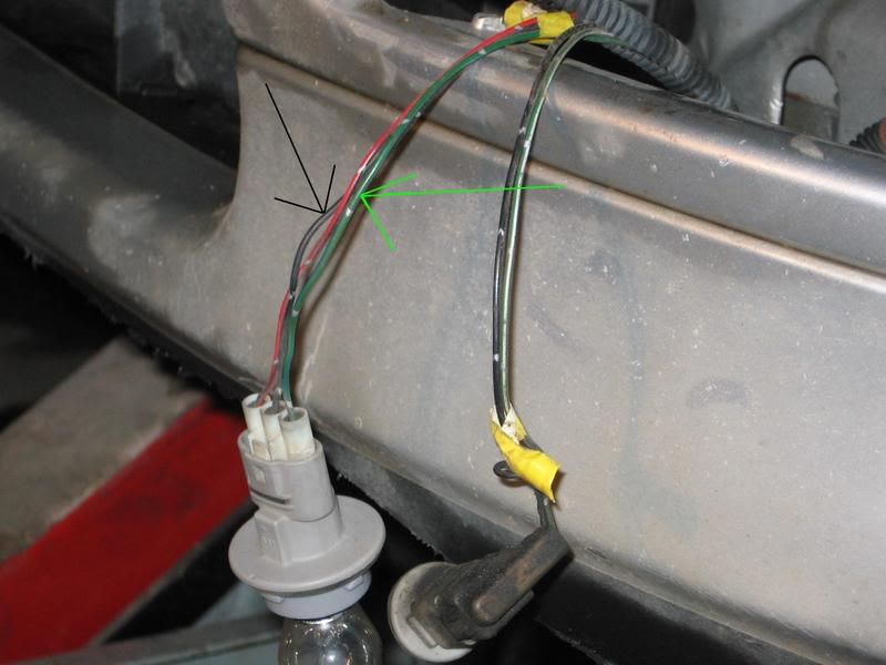
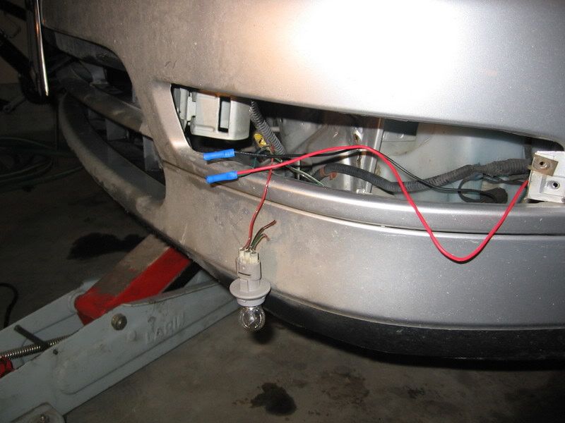
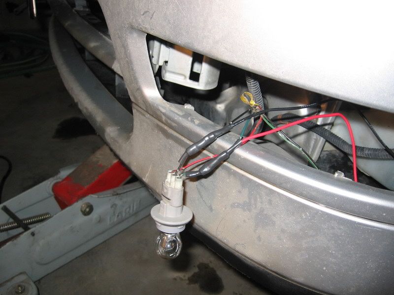
Next we will begin wiring the lights. Jack the car up and remove the fender well. Get your harness and plug it into the side marker, running the rest of the wire up to the front of the car. Remove the bumper lights and cut the GREEN and BLACK wires(Sidemarker will only flash with turn signal as the JDM ones only flash) as shown below. Using the connectors, splice into the factory wires and connect the wiring harness, test, then shrink wrap.


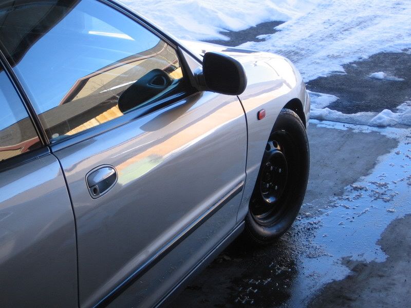
Now you can replace your bumper lights, Put the Sidemarkers in and step back and enjoy.


The following write up is for those interested in changing how your sidemarkers illuminate:
All pictures and write up in above quote is property of danomatic93 at jdmuniverse.comdanomatic93 said:Background info:
Our corner lamps are dual filament bulbs which have 3 wires:
Red +12V parking lamp
Green +12V blinker
Black 0V ground
(colors may vary, check your manual or use a multimeter)
The sidemarker has a single filament, which has 2 wires:
Red +12V
Black 0v ground
How do you want it to be wired? There are 3 options...
Option 1:
-Sidemarker is illuminated (providing your parking lamps are on)
-Otherwise, sidemarker is off (it will not blink)
Option 2::
-Sidemarker and blinker blink in phase (at the same time) whether or not Parking lamps are ON.
-Otherwise, sidemarker OFF
Option 3:
-Sidemarker and blinker blink out of phase (alternate illumination)
-Otherwise
(a) Parking lamps ON: sidemarker is illuminated
(B) Parking lamps OFF: sidemarker blinks in phase with blinker
How do you wire them up?
Option1-
Connect Red to Red.
Connect Black to Black.
Option2-
Connect Green to Red.
Connect Black to Black.
Option3-
Connect Red to Red.
Connect Green to Black.
The reason/how option 3 works…
When the parking lights are on, +12V is on the positive side of the sidemarker and the blinker, being off, sends no voltage (0V) to the negative side. This +12V illuminates the bulb. Now, when the blinker is activated, +12V pulses are observed on the negative side. This means that there is +12V on BOTH sides of the bulb, which because of the lack of voltage difference, the bulb turns off. This is also why the blinker and sidemarker alternate illumination.

Link Provided by: XslickwhitetegX
I do not take credit or responsibility for these links
Users who supplied information do not take any responsibility in you cutting into your own cars. ALL tasks are performed at your own risk!!


